- Compatible with AvrStudio
- Supports all AVR Controllers
- Parallel and serial High-Voltage-Programming
- Small and easy layout with only a few parts
- STK500 protocol
- Schematics and board layout available
The project started as an enhancement of Martin Thomas Evertool project.
He has rebuilt the AVRISP and JTAG adapter with only a few parts.
Unfortunately they both don't support high-voltage programming modes -
the only possibility to 'rescue' AVR controllers when you e.g. disabled
the reset or SPI fuses. The only widely available possibility was the STK500 from ATMEL.
HVProg is a redesign of the original STK500 without all components of a
development board. It is based on the original ATMEL schematics that are
freely available on the net (e.g. at avrfreaks.net).
The main target was to keep all nessecary functionality to programm all
available AVR controllers in every programming mode that the STK500
supports.
If you look for a development board for ATMEL AVR controllers you better buy the original STK500. If you only need an ISP programming adapter the AVRISP included in Evertool is better suited for you!
Please consider:
- HVProg can't replace a real development board and will never do
- No ESD protoction
- HVProg in the Basic-Version needs a stabilized 12V and 5V input voltage
- For one step a working programmer is needed (AvrProg compatible prefered, see software section)
- HVProg has only been tested in 5V environments
There are two versions of the project available:
- The Basic-Version has seperate connectors for the different programming modes and is only
available as schematic.
It needs a stabilized 5V and 12V input voltage and is supposed to be
used for own board development. This version will not be updated
except to the correction of errors.
- The Advanced-Version is available as schematic and
board layout. Adapter boards for HV-Programming will be ready soon and a
good tutorial how to build a case for HVProg is linked. This version
needs an unstabilized input voltage of at least 15V (AC or DC).
Basic-Version
- 6 Pin ISP
- 10 Pin ISP
- Serial-High-Voltage Programming (no standard connector)
- Parallel-High-Voltage Programming (STK500 compatible control und data connectors and one connector with other needed signals)
Advanced-Version
- 6 pin ISP
- 20 pin connector for ISP, parallel and serial high-voltage programming
- 03.10.2004 -> First version released (V0.2)
- 05.10.2004 -> Schematics as eagle file released
- 06.11.2004 -> Version 0.3 with less parts
- 24.04.2005 -> Completely updated site with lots of new infos
- 29.09.2005 -> Programming problem solved. See Software-Section
Copyright
The schematics, boards and every other available information on this site are freely available for noncommercial use only.
I am not responsible if anything get damaged by my circuits or by false information provided or any other reason.
I am also not responsible for linked content. These sites are property of their owners.
Basic-Version (v0.3)
Advanced version (v0.5)
- ISP: The connector is compatible with the ATMEL standard (see STK500 User Guide page 51)
- HV-Seriel: (For exact pinning check the appropriate controller datasheet. Section Memory Programming/High Voltage Serial Programming)
| Pin name |
uC pin |
| SWCLK |
XTAL1 |
| TRST |
Reset (High Voltage Enable Jumper must be set) |
| PPD0 |
'Serial Data Input' (usually PB0) |
| PPD1 |
'Serial Instr. Input' (usually PB1) |
| PPD2 |
'Serial Data Output' (usually PB2) |
- HV-Parallel: For special connections check STK500 User Guide (Table 3-3 page 21, look for BSEL2 and PJUMP)
| Pin name |
uC pin |
| VCC |
target supply voltage uC |
| GND |
ground |
| TRST |
Reset (High Voltage Enable Jumper must be set) |
| SWCLK |
XTAL1 |
| PPC0 |
If BSEL2 then connect to PortA.0 otherwise not needed |
| PPC1 |
PortD.1: Rdy/Bsy |
| PPC2 |
PortD.2: OE |
| PPC3 |
PortD.3: WR |
| PPC4 |
PortD.4: BS1 |
| PPC5 |
PortD.5: XA0 |
| PPC6 |
PortD.6: XA1 |
| PPC7 |
PortD.7: PAGEL |
| PPD0 |
PortB.0 |
| PPD1 |
PortB.1 |
| PPD2 |
PortB.2 |
| PPD3 |
PortB.3 |
| PPD4 |
PortB.4 |
| PPD5/MOSI |
PortB.5 |
| PPD6/MISO |
PortB.6; if PJUMP connect it to PortC.0 |
| PPD7/SCK |
PortB.7; if PJUMP connect it to PortC.1 |
- External clock to reanimate controllers with wrong
clock settings (fuses) is available SWCLK. The external clock has to be
connected to XTAL1 and can be adjusted up to 3,69MHz with the STK500
plugin in AvrStudio.
The original ATMEL firmware is available in .ebn format that is only supported by AvrProg (included in AvrStudio).
When you have the original Avr910 programmer or an improved version (like the one from Klaus Leidinger [German Site]) you can directly flash the firmware in the At90s8535 or Mega8535 (won't work with original Avr910).
The file you need is in the AvrStudio directory: ".\Stk500\stk500.ebn".
Software installation:
- Connect the ISP programming adapter with your computer and the ISP port on the HVProg board
- Mount the 'Selfprogramming' jumper to pin 1,2
- Connect the power supply (Basic: only 5V supply needed. Advanced: Regular supply)
- Start AvrProg (AvrStudio: Tools/AvrProg)
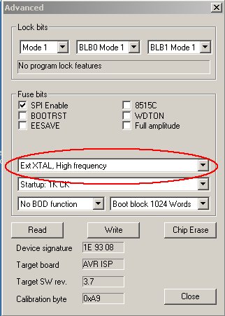
- Select 'stk500.ebn' and set the appropriate fuses (ext. high frequency crystal, only for Mega8535)
- Flash the firmware
- Disconnect power supply and then the programming adapter
- Mount the 'Selfprogramming' jumper back to pin 2,3 (default)
Important:
If you use Klaus Leidinger's programmer please upgrade its firmware to
version 3.8.
Otherwise you might get problems when you use a Mega8535.
How to set the Fuse-Bits:
When writing the firmware with Klaus Leidinger's programmer you get a write error (90s8535 only)
The problem is known and results in a bug in the programmers firmware. An Update is available here and should be used to prevent errors.
HV-Programming is not working with Basic-Version
The 12V power supply must be between 11.5V and 12.5V otherwise the programming mode cannot be entered.
HV- and/or ISP-Programming modes are not working
The 'Selfprogramming' Jumper must be placed at pin 2,3. For HV-Mode the 'High Voltage Enable' jumper hast to be mounted, too.
Can i use HVProg with the new 2.x firmware?
Yes, the original STK500 is completely simulated. All future firmware version should work without any problems.
Here are some rebuilds of the original HVProg available which are slightly modfied to suit special conditions.
It is possible that some of the specifications given above are NOT correct for these rebuilds!
* * * *
I want to thank all the people from mikrocontroller.net forum
and especially Klaus Leidinger for his board layout and his great help.
Tobias Hammer

|