Atmega fusebit doctor (HVPP+HVSP) – fix the fusebits
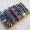 Atmega
fusebit doctor, as name says it, device for repairing dead Atmega (and
Attiny from v2.04) family AVRs by writing correct fusebits. Most common
mistakes or problems are a wrong clock source (CKSEL fusebits), disabled
SPI programming (SPIEN fuse) or disabled reset pin (RSTDISBL fuse).
This simple and cheap circuit will fix you uC in a fraction of a second.
If in first case we can help ourself with clock generator, then in 2nd
and 3rd cases bring uC back to life is impossible with standard serial
programmer. Most of people do not decide to build parallel programmer
because its inconvenient and its cheaper and faster to buy new uC.
This circuit uses the parallel and serial high-voltage programming
method. With those methods, we can talk to our “dead” chips which have
reset or isp disabled:
HVPP = high voltage parallel programming.
HVSP = high voltage serial programming.
Supported chips list:
Code to this point supports 145 chips, but not all have been tested. Tested are lighted green. Report a problem – and i make a fix :)
1kB:
AT90s1200, Attiny11, Attiny12, Attiny13/A, Attiny15
2kB:
Attiny2313/A, Attiny24/A, Attiny26, Attiny261/A, Attiny28, AT90s2333, Attiny22, Attiny25, AT90s2313, AT90s2323, AT90s2343
4kB:
Atmega48/A, Atmega48P/PA, Attiny461/A, Attiny43U, Attiny4313, Attiny44/A, Attiny48, AT90s4433, AT90s4414, AT90s4434, Attiny45
8kB:
Atmega8515, Atmega8535, Atmega8/A, Atmega88/A, Atmega88P/PA, AT90pwm1, AT90pwm2, AT90pwm2B, AT90pwm3, AT90pwm3B, AT90pwm81, AT90usb82, Attiny84, Attiny85, Attiny861/A, Attiny87, Attiny88, AT90s8515, AT90s8535
16kB:
Atmega16/A, Atmega16U2, Atmega16U4, Atmega16M1, Atmega161, Atmega162, Atmega163, Atmega164A, Atmega164P/PA, Atmega165A/P/PA, Atmega168/A, Atmega168P/PA, Atmega169A/PA, Attiny167, AT90pwm216, AT90pwm316, AT90usb162
32kB:
Atmega32/A, Atmega32C1, Atmega323/A, Atmega32U2, Atmega32U4, Atmega32U6, Atmega32M1, Atmega324A, Atmega324P, Atmega324PA, Atmega325, Atmega3250, Atmega325A/PA, Atmega3250A/PA, Atmega328, Atmega328P, Atmega329, Atmega3290, Atmega329A/PA, Atmega3290A/PA, AT90can32
64kB:
Atmega64/A, Atmega64C1, Atmega64M1, Atmega649, Atmega6490, Atmega649A/P, Atmega6490A/P, Atmega640, Atmega644/A, Atmega644P/PA, Atmega645, Atmega645A/P, Atmega6450, Atmega6450A/P, AT90usb646, AT90usb647, AT90can64
128kB:
Atmega103, Atmega128/A, Atmega1280, Atmega1281, Atmega1284, Atmega1284P, AT90usb1286, AT90usb1287, AT90can128
256kB:
Atmega2560, Atmega2561
About:
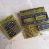
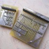
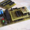
Just put your dead mega in socket, press the START button, and enjoy your good-as-new processor. There are three slots on board, for most common AVR’s, pins compatible with: Atmega8, Atmega16, Attiny2313. There is also an extra goldpin connector with all signals so you can attach adapters:
“#1 adapter” as HVPP extension, for 20pin Attiny26 compatible and 40pin Atmega8515 compatible processors.
“HVSP adapter” for 8pin and 14pin HVSP processors.
Or make your own adapters for other types of processors, in trough-hole
or surface-mounted, you can use the breadboard for this – just connect
signals to correct pins. How? Check your AVR datasheet, go to “memory
programming” and then “parallel programming” – check the signal names,
all signals are described under the DIP40 slot. In doctor memory there
is a lot of free space so project may be developed all the time. One
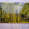
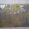
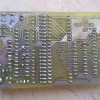
sided PCB with 55mm x 92mm dimensions. On top side you need to solder
several jumpers, or, make this PCB as double sided – choose yourself.
Resistors from R7 to R23 may be in 100ohm to 10K, but i suggest from
470ohm to 1K.
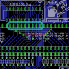
ATTENTION!
While mounting the DIP40 slot, you must to remove it pins from 29 to
37. These pins must not have electrical contact with inserted uC pins,
traces runs there only to make the board smaller (onesided). Take a look
at pic on the left, these you must remove from slot.
Usage:
The ALLOW ERASE jumper allows doctor to erase whole
flash and eeprom memory, if it is open, doctor will newer erase memory
but may not cure device if lockbits are enabled, so you choose. After
insert dead uC and press the START button, doctor will
initiate the parallel or serial high-voltage programming mode. This is
chosen automatically, device will recognize HVSP adapter and start to
work in HVSP mode. After that, doctor wait for high state at RDY/BSY
line. Then, read device signature and check if it supports it. Next,
memory erase is performed if user allows that. Then lockbits are
checked, and if they not blocking device, doctor sets all fusebits to
fabric, having regard to whether there are extended fusebits or not.
Some of older AVR have only one byte of fuses – LOW – and this is also
included. After fusebits are verified, the proper leds is flashed.
Leds explanation:
green on – patient
successfully cured, fusebits repaired. If lockbits are enabled, just
verify fusebits with factory ones – and if they ok – light up green.
red on – signature problem, can’t read, no device in socket, or no such signature in database.
– signature ok, fusebits are wrong. Lockbits enabled, chip erase permission required (read below).
– signature ok, no lockbits, but for some reason can’t write new fusebits.
Terminal:
Note that terminal is not needed, device works without pc, and all we want to know we get from leds.
You can find extra RS232 output, and connecting this to the terminal,
sends all information about fixing process – see exemplary printscreens
in gallery. All the info is send “on fly” via uart. Use proper converter
to connect this with pc. If you have COM port for RS232, use MAX232
based converter (eg this). If you are using laptop, use the USB converter (like this or this).
Terminal settings:
baudrate: 4800
parity: none
databits: 8
stopbits: 1
handshake: none
Other:
Use one of the following microcontrollers as the doctor-chip: Atmega8,
Atmega88, Atmega88P, Atmega168, Atmega168P, Atmega328, Atmega328P – and
their newer/low-voltage “A” or “L” versions.
Use stabilized 12V supply voltage. Higher voltage can damage fixed chip!
Code was written based on high-voltage parallel and serial programming section of datasheet of suitable AVRs.
If you are searching for attiny family AVR’s fusebits fix device, then check my previous project, the Attiny fusebit doctor.
Unfortunately, some bugs show off and this project is no longer updated
since the “Atmega fusebit doctor” supports all the Attiny family AVRs.
But, source code is attached for this project, and with avr datasheet,
it will be easy to understand this programming mechanism.
Fusebits:
Internal 1MHz clock, and enabled EESAVE bit – see README file.
If you use a brand new chips as doctor, you don’t need to change
anything – 1MHz clock is already set as default. EESAVE bit is optional.
It disallows to erase the eeprom when firmware is actualized, eeprom is
used to store the fixed chips counter which is send trough uart.
Send your own fuses and locks trough terminal, talk with chips with broken signature. If you connect terminal Tx pin to PCB Rx pin – manual mode will be enabled automatically. This requires Tx-terminal pin to be HIGH and OUTPUT when idle. It must pull up the 10K pulldown. If this condition is not met, doctor will work in normal – automatic mode.
HOWTO:
First, doctor will read signature. And if fail, it will ask to type signature manually.
Type two last bytes of signature in HEX (4 chars) and hit enter.
Then, doctor will try to read the chip depending on given signature.
When succeed, select an option:
1 – write fusebits – this will perform a fuse write cycle with fuse-values from buffer (default).
2 – modify fusebits – this will let you to type fuses
manually, values in buffer will update. Type one byte in HEX (2 chars)
and hit enter. Repeat for each byte (if exist).
3 – set lockbits – type new lock value in HEX (2 chars) and
hit enter – do this with caution! Remember that unused bits are always
1! E.g. if want to enable LB1 and LB2, type FC (11111100)
4 – erase the chip – this will just erase the chip and locks, it require “allow erase” jumper for safety.
5 – end – exit programming and drop voltages, now you can safely remove the chip.
See how Attiny13 with broken signature was repaired.
See how the same chip was “broken” again.
Do not suggest LEDs when in manual mode – they just blinking randomly :)
ATTENTION – Firmware 2.1x NEED a pcb updated to version 2h!
Gallery:
Files:
 DOWNLOAD – ARCHIVE of all previous updates. Firmwares + boards.
Changelog in README file. -SMD VERSION HERE-
No need to download this, all newest files are below.
 DOWNLOAD – UPDATE #11, 30.04.2011:
Firmware ver.2.11 – fixes
Fusebits: see README file
Fixed bug when not writing the HIGH fusebyte (concerns all chips!)
“Just” a typo which i made during optimalisations for 2.10 firmware :)
 DOWNLOAD – SMD Adapter:
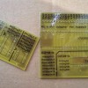
Pads for 4 chips, compatible with: T2313, M8, M16, M128 – all has been tested.
Use strong paper clips to push chip to the pads.
Notifications about new updates – twitter.com/manekinen
FAQ – frequently asked Questions and Answers: (update 2014-02-01)
Q: No sign of life, no leds are working.
A: Critical bugs on pcb, poorly programmed chip.
Q: Red led is on.
A: Chip si not recognized. Make a voltage measurements. In idle,
measure voltages on +12 RESET and +5 SUPPLY at female goldpin connector –
you should get 0V or close to 0V on both. After the START button is
pressed, you should get close to +12V and 5V for one second. If not,
check transistors, if they are ok and if they are soldered ok.
Q: Red led is on.
A: Bugs on pcb, traces are packed densely and its very possible
that you have invisible gap, shortcut, or dry joint. Check everything
with multimeter, but PRECISELY.
Q: Red led is on.
A: Connect device to the terminal to get repair log. Press start to receive infos.
Q: Received “Init programming…” and nothing more – OR – received signature is “00 01 02″ or “FF FF FF”.
A: Chip is broken, or there still are bugs on pcb – look above.
Q: Received signature is “1E 90 00″, ” 1E 1E 1E”, or something familiar (meaningful data).
A: Chip is good, it initiates, look for shortcuts on DATA, BS, XA lines.
Q: Green led is on / “Verifying… – OK!” received, but chips don’t work with standard programmer.
A: You can be 100% sure that fuses are fixes, chip have hardware ISP damaged or it have some other damage.
Q: What are “Read Signature… FAIL!” and “Trying T2313 pinout… OK” doing in log?
A: Alle the 20pin chips need to be threated individually. First,
device tries to read chip with standard schematic, and if it fails
(“FAIL!”), then it tries to use schematic for 20pin T2313 compatible
chips and then chip is read properly. This is normal behavior, this not a
bug.
Q: What are “<[2J" trashes doing in log?
A: This is a terminal clear screen sequence, turn on the “VT-100″ emulation in terminal settings.
Q: I’m trying to type data into terminal but no chars appearing.
A:Make sure you set handshake to NONE in terminal settings.
Q: After typing data into the terminal, i can’t confirm them with return key and can’t type next ones.
A: When pressing return, your terminal must have to send the CRLF chars, if not, check your settings.
Q: This still doesn’t help me, i tried everything but still have the problem.
A: Ask in comments below :) Post firmware version and pcb version with which you try to work, paste the repair log.
Q: Do all these 1K series resistors (R7 up to R23) are really needed here?
A: No, you can build the circuit without them. But remember, if
for some reason out patient will not enter in the programming mode and
continue with its code, then logic state conflict will occur between two
microcontrollers which can damage them permanently. These resistors are
to protect the circuit against such situations. I strongly recommend to
build it exactly as schematic says.
Q: Pulldown resistors for 12V and 5V lines (R24 and R27) are
heating up quite strongly in manual mode, and whole circuit takes more
power, can i change them for something higher value?
A: Yes, but circuit can work incorrectly with some of the
patients. When idle, voltages should be near 0V, and when powering on or
off, their edges should have proper steepness to provide good timing
(see entering high voltage programming in datasheet). Because only
simple bipolar transistors are used, these resistor guarantee above
requirements. The interesting case is an attiny2313 problem when all the
fuses were correctly burned, without one, the RSTDISBL. As it showed
up, because of bad edges of 12V reset voltage, this uC although was
working in parallel mode, but not in high voltage, so it was not
allowing to change that fuse – this is my own interpretation so i can be
wrong.
Q: My chip is read properly but doctor can not write new fuses, allow erase is enabled.
A: If the ISP programmer acts the same way, then your chip is damaged, nothing can do.
Q: Without a patient, circuit acts awkward, it freezes, and goes on when i put my finger near the traces.
A: This circuit is not meant to be used without a patient. It
acts in such way because when entering in programming mode, it is
waiting for a high state on the RDY pin from patient. This pin is not
pulled down and works as high impedance input, so electrostatic charge
from your finger is read as high state and code goes on further.
Q: Chip names are not appearing in the log, i see “no names in 8kB ver” instead.
A: Chip names are not displayed in 8kB versions of the firmware,
i.e. for atmega8 and atmega88 – because names don’t fit in such memory
space. If you want the names, use atmega168 or atmega328 chip and burn
proper firmware.
ALWAYS use the newest version of the firmware. Hex and bin files are the flash memory files, use one of them. No need to program eeprom memory.
 – Русский перевод – Евгений из GetChip Блог.


 3 May 2010
|
Posted by admin

 Categories:
  Tags:
Tags: 


Czytałem kilka razu opis ale nie wiem jak przejść na automatyczny :( Zmieniłem tranzystory sterujące linie reset i program ruszył odczytał fusebity i zapalił zielona dioda i tera świeci ciągle. Jak przejść na tryb automatyczny?
Wielkie dzięki za pomoc
Udało mi się przejść na automatyczny tryb. Miga ciągle czerwona dioda.
AUTOMATIC HVPP MODE
Init programming… DONE
Read signature… 1E 98 01
Searching chip… Atmega2560
Chip erase… DONE
Read fusebits… L:62 H:D2 E:FF
Should be… L:62 H:99 E:FF
Lockbits… DISABLED (FF)
Writing 62 99 FF… DONE
Verifying… L:62 H:D2 E:FF- FAIL!
Please try again…
Thank You
To chyba nie wróży nic dobrego :(
Jakieś 2 tygodnie temu to samo stało się mi z poprzednia atmega2560.
Proszę o pomoc
Komunikacja wygląda dobrze, także na płytce/stykówce błędów raczej nie masz, możesz dla pewności podpiąć jakiś zdrowy układ aby się upewnić.
Z tego co widzę po fuskach to bit SPIEN jest włączony, wewnętrzny zegar z podziałem na 8 aktywny, więc komunikacja z programatorem ISP chyba jest?
To nie wygląda dobrze, miałem już przypadki że pamięć “zamarzała”, czytać się dało układ nawet działał ale zapisać już nie. Sprawdź swój układ w którym używasz tej 2560, źle zaprojektowane zasilanie, szpilki itd mogą być powodem takich uszkodzeń. Również samo programowanie przy niestabilnym zaśmieconym zasilaniu, lub mocno przetaktowanym uC, jest dosyć ryzykowne. Pod tym projektem jest już prawie tysiąc komentarzy, sporo dziwnych przypadków uszkodzeń można w nich wyczytać.
Podłączyłem programator usbasp za 10 razem udało mi się odczytać sygnaturę (korzystam z MKavrCalkualtor) po czym znów przez 10 razy nie mogłem jej odczytać. Ale gdy znów się udało to spróbowałem zmienić fusebity. Odznaczyłem podział prze 8 i zaznaczyłem taktowanie wewnętrzne 8Mhz. Przy zapisie wyświetlił się błąd weryfikacji i już nie mogę odczytać uC. Przy ostatnim wgrywaniu programu miałem podpięta kartę SD do uC może ona zakłócała transmisję.?? Chyba to już koniec z nimi :( :(
Ciągle podajesz za mało szczegółów. Czy ten uC siedzi obecnie w jakimś układzie z innymi peryferiami? Jego linie są przez nie obciążone? Pisałeś o karcie SD, co z poziomami napięć? Jak je konwertujesz? Jakim napięciem zasilasz cały układ, jakimi napięciami programowałeś przez programator ISP? Podejrzewam że masz jakiś okropny błąd w schemacie/płytce i dla tego są takie jaja, jeśli tego nie wyeliminujesz to uszkodzisz kolejne procki. Poproś na jakimś forum o weryfikację twojego układu, możesz również wrzucić go tutaj, mogę zerknąć.
I wonder how HVSP and the automatic recognition works.
I can’t find a schematic or PCB for the HVSP Adapter in the arcives. There are only some GIF files but the Names on the Pins are other than the Names on the AVR-Doc PCB.
I have a ATtiny85 with disabled Reset. I tryed to find out the connections from the photos and soldered the ATtiny to the AVR-Doc with some wires.
P0 -> XA1
P1 -> XA2
P2 -> BS1
P3 -> RDY
P4 -> PAG
P5 -> +12V
VCC -> +5V
GND -> GND
But the AVR-Doc stays in HVPP mode and doesn’t recognize the ATtiny.
What’s the problem?
Hello. Download #11 update, pcbs and schematics for adapters are in the “adapters” folder.
HVSP adapter recognition is made by detecting connection from XTAL1 to OE (see hvsp adapter schematic).
Witam. Zbudowałem układ w najnowszej wersji na uniwersalnej płytce drukowanej i mam dziwny problem. Gdy w podstawkę 40 pin włożę ATmega16A wszystko działa prawidłowo, zapala się zielona dioda. Kiedy włożę ATmega644PA układ nie daje znaków życia, nie zapala się żadna dioda. Nie wiem, czy to uC jest uszkodzony, czy coś innego. Proszę o pomoc.
Najprawdopodobniej to trup. Możesz jeszcze sprawdzić co sie pokazuje w terminalu, ale podejrzewam że nawet nie wchodzi w tryb programowania.
Powiem Tobie, że.. ATmega644PA działa! Wiesz, jak to zrobiłem? :) Już praktycznie nie dając sobie nadziei na jej działanie: wziąłem kawałek kabla, jedną końcówkę podłączyłem do 5V na płytce, a drugą zwarłem z wyjściem TxD mojej ATmega644. Po opisie układu doszedłem do wniosku, że to może tak działać. Udało się! Z początku miałem jakieś dziwne problemy, bo raz mrugała zielona dioda, drugim – czerwona, aż w końcu na stałe zaświeciła się zielona! Ucieszony wyjąłem uC i włożyłem w płytkę stykową, gdzie miałem podłączony programator. Program wykrył ATmege prawidłowo. Dzięki za takie urządzenie, bo bez niego bym musiał wydawać kolejne 30zł ;)
Pozdrawiam
Że co? Skąd taki pomysł? Przecież to bez sensu i nie ma prawa działać. Lepiej poszukaj błędu na płytce bo coś może nie łączyć.
Witam!!
W całym tym układzie brakuje mi tylko jednego , w trybie manualnym powinien być jeszcze jeden punkt w którym możemy sobie znienić sygnaturę procka mimo że układ odczyta sygnaturę,
spotkałem się z atmegami które miały zmienioną sygnaturę przez “Arduino” i ni jak nie można przywrócić właściwej sygnatury,np.
Mega328 miała po “Arduino” końcówkę sygnatury “14” a powinna mieć “OF”.
Pozdrawiam serdecznie !!
maciej
Sygnatury nie da się zmieniać. Czasem zostaje ona zmieniona na wskutek jakiegoś błędu, taka przypadłość avr.
Znalazłem błąd. Po podłączeniu AtMegi8 układ zaprogramował na 2MHz, a nie na 1MHz, jak powinno być fabrycznie.
Nie nie, układ ustawia E1 D9 co oznacza 1MHz. Jeśli wskakuje co innego to szukaj błędu w innym miejscu.
Zwracam honor. Do grupy AtMeg8 wpadła mi jedna AtMega88 i akurat ją wziąłem do przetestowania. Układ działa tak jak trzeba :)
Hi
I’m getting Received “Init programming…” and nothing more (without patient).
Even if I’m taking chip (Atmega328) out of the doctor and just trying to power it – result is the same. stuck on “Init programming…”. Fuses are 0x62 0xD9 0x07.
While in this state, there is +5V on PIN-13 (constantly)
Tried with 2 chips (Atmega328 and Atmega328P) – same result. Any idea ?
I think i don’t understand what are you trying to do. Run the circuit without a patient chip? Why?
I had the same result as you did. The posted video here, shows a no chip condition posted on the terminal. Apparently older versions of the firmware worked this way. The newer 2.1X terminal UPDATE doesn’t seem to give a “no Chip” result, it just hangs on Init programming like you said. Put in a chip and push the button, it should start after that. It seemed like before I flashed the exteneded fuse to 07 from FF, I don’t remember it doing that.
manekinen,
I’m trying to troubleshoot the board, so I’m powering the chip outside of a board and expect to get “No chip in socket” result, but it’s not happening. It’s stuck on “Init programming…”
Is it a correct behaviour of 2.1X as Russell saying ?
No, you wont get it. The behaviour is good, it waits for respond from patient, there is no timeout for this (but yes i should implement some timeout). Powering it without a patient is pretty pointless.
I understand your thought; why power without a patient, but I sometimes do that myself. Circuit wise, would it be feasible to add say, a 10K pull down to ground on RDY pin, or even to vdd. That way at power up RDY pin would set, and when a chip was placed and read button was pushed Doctor would start again. Possible ciruit remedy?
Well, you can add this pulldown resistor if you want (avr dont have internal pulldowns). But this wont solve the lack of “no chip” message, it will still wait for RDY signal. I think i can add a 1 second timeout for RDY in the final update, so it will say “no chip” after not getting this signal after 1 second.
The “no chip” is really nice, but I would rather the circuit not hang in initial programming, looking for a chip that is not present. Like Yuri mentioned, +5 stays high until the RDY is found. It’s an extended 50 Ma draw through the 100R resistor, does heat up a bit. I think it’s a worth while update if you have time, and would be greatly appreciated. Thanks
“no chip” + release the voltages, both of them, because 12V is also present.
Sounds good. To be honest I am very pleased with this cicuit now. The ATMEGA FUSEBIT DOCTOR and the Uprog Programmer are two of the best, most useful projects I’ve built lately, Thank you for sharing. Wish I could see the source code, but I understand. These are of course not bugs, but if you are making an update and you feel these would work acceptably, nice little refinement.
hello
I have a mega32 with a problem. when i press the botton LED is going to turn off .whats the problem?
I had the same problem with tiny2313. I used terminal by RS232 and i put uC signature manually. Probably signature of you atmega is broken.
Sorena, check FAQ section first (above), should help.
please insert sorce bascom
Большое спасибо за полезный девайс!
Manekinen
Is there a reason 100R value is used for R25 pull down resistor. A 1K resistor should give the same result with only a 5 milli amp draw instead of 50 MA. I read your old post from December 2010, and why a pull down was needed for Attiny 2313.
You can mod this circuit if you want. If 1K works for you, no problem. 100ohm is guaranteed value for all avr’s.
And also, 2.12 update is coming up (slowly). This is the last update ever, so if someone has any suggestions etc, please contact me or post in comments.
Here are my thoughts on what is already a great circuit, if this explanation is of help for your final update. I sometimes like to power FUSEBIT DOCTOR without a patient, because powering with a patient, patient is automatically fixed without pushing the start button. This is what’s supposed to happen, but I sometimes like to read what fuses are in terminal before fix, for help in troubleshooting. If I connect powered UART cable to un powered FuseBit Doctor (so Doctor will start in manual mode), Fusebit Doctor seems like it tries to power through UART. So I power FuseBit Doctor with good chip to set RDY, then I can connect UART and broke chip in socket so I can read fuses in terminal, without the chance of reset first. The “no chip” and voltage release are nice refinements, and may already take care of this. If this makes sense to you it may help in how you put your final code together.
Thanks
http://forums.adafruit.com/download/file.php?id=13724
This is not the fanciest version, but how I built mine. I need an adaptor for all chips other than 8 series, my most used chips. I made an adaptor for the Attiny 2313.
Ok i see where is the problem. When i add the no chip timeout, then you be able to connect 12V supply to the board, pass the chip check, and then safely insert your patient without fixing it automatically.
Your link returns 403 forbidden, i think they require to be logged in to download anything.
Cześć mam kilka pytań, zrobiłem fusedoctora udało mi się odblokować M32 wiec zakładam że doktor działa. Ale mam następujący problem próbowałem naprawić procki M8, M168 oraz Attiny2313 i tak dla procków M8 oraz M168 doktor rozpoznaje sygnatury procków, mogę zmienić fusy, doktor pokazuje że naprawił procka i teraz po włożeniu tak naprawionego procka do docelowego układu nie da się go zaprogramować (testowałem na usbasp oraz stk200) czy to znaczy ze proc jest do kosza ?? Z kolei Attiny 2313 nie jest w ogóle rozpoznawany – a na pewno jest sprawny bo był wyciągnięty z działającego układu – jaką wersję softu powinienem wgrać do mojego doktora zbudowanego na M8??
I jeszcze jedno czy istnieje wersja softu do doktora w której terminal działałby z baudrate: 9600?? Jeśli nie to czy można prosić o taką wersję??
Z góry dzięki z odpowiedz.
Pozdrawiam,
D
Cześć
Jaki błąd zwraca oprogramowanie od usbasp przy próbie zaprogramowania tych procków?
W jaki sposób 2313 nie jest rozpoznawany? Skąd to wiesz skoro nie masz terminalu (chyba?). Mogą być błędy na płytce, mimo tego że M32 działa.
Wersja softu oczywiście najnowsza, 2.11.
Nie ma innych opcji baudrate tylko 4800. A czemu akurat chcesz 9600?
Po kolei:
Przy próbie programowania tych naprawionych procków dostaję następujące komunikat:
avrdude: error: programm enable: target doesn’t answer. 1
avrdude: initialization failed, rc=-1
Double check connections and try again, or use -F to override
this check.
Terminal oczywiście posiadam w załączeniu screeny z podłączonym do fusedoctora Attiny3213 oraz M8 (PCB sprawdzałem 17 razy i wydaje się że nie ma zwarć ani zimnych lutów).
Wersja z baudrate 9600 była by pomocna ponieważ w laptopie nie posiadam portu szeregowego (i muszę używać przejściówek – plątanina kabli :( ), za to mam BT oraz moduły bt/rs232 ale te niestety albo mają na stałe ustawiony baudrate na 9600, albo minimalny baudrate jest 9600.
Pozdrawiam,
D.
Coś nie działa dodawanie zdjęć, może wiec tak zadziała:
http://www.fotosik.pl/pokaz_obrazek/a35e4df2771f38f2.html
http://www.fotosik.pl/pokaz_obrazek/a021a6423eab754f.html
Wygląda na to że procki są naprawione. Płytke masz na pewno ok. Albo masz problem z programatorem ISP (niestabilne zasilanie, długie przewody, itd), albo oba procki mają uszkodzone sprzętowe SPI – mogą paść podczas programowania przez ISP (niedopasowane poziomy napięć, konflikty logiczne). Jeżeli możesz wyeliminować pierwsze podejrzenie poprzez programowanie innej sztuki tego samego modelu, to procki są uszkodzone.
Następnym razem po prostu wklej tekst z terminala zamiast kombinować ze screenami :)
BTW wcześniej źle przeczytałem Twój komentarz (jeszcze kawa nie działała), że procki nie są rozpoznawane, ale już się wyjaśniło :)
Oba programatory (usbasp oraz stk200) mam sprawne, kable nie są długie, zasilanie stabilne – z resztą inne procki da się nimi zaprogramować – a wiec obawiam się że zdechło SPI w moich naprawianych prockach. Zastanawiam się nad jedną rzeczą w filmie demo procesu naprawy (trzeba przewinąć do 1m30s) jest podłączony ATTINY 2313 i jest tam takie coś:
sygnatura jest ff:ff:ff – FAIL!
trying T2313 pinout – 1E 91 0A
searching chip .. Attiny2313
etc…
A na pierwszym planie pojawia się napis RECOGNIZED AND FIXED – czy to znaczy że pomimo braku poprawnej sygnatury dla tego procka (attiny2313) jest on sprawny ?? Mój ATTINY po włożeniu do fuse doktora i próbie rozpoznania rzucił podobny ekranem jak na filmie, tle że po wyjęciu z fuse doktora przestał działać w układzie z którego został wyjęty :(.
I jeszcze jedno pytanie mój fuse doktor wyświetla w:
searchin chip … no names in 8kB ver.
Na filmie w tym miejscu pojawiają się nazwy procków – czy zatem moja wersja oprogramowania fuse doktora jest OK ??
Ze screenami musiałem kombinować bo w moim ubunu srodowisko graficzne nie wspiera wszystkich operacji copy/paste :(.
W takim razie, jeśli weryfikacja fusków przebiega pomyślnie a programator ISP nadal ich nie widzi, z 99% prawdopodobieństwem mogę stwierdzić że padły im SPI. Miałem tak raz z atmegą32.
Co do drugiego pytania, odpowiedź jest w FAQ:
To co masz w drugiej linii wklejonego przez Ciebie logu, to jest właśnie sygnatura.
Nazwy układów nie wyświetlają się w 8kB wersji wsadu, (dla mega8 i mega88) bo się nie mieszczą w pamięci, stąd taki komunikat. Jeśli chcesz aby wyświetlało nazwy, musisz do budowy doctora użyć mega168 lub mega328 i wgrać odpowiedni wsad.
Bo zresetowałeś mu fuski, lub też wykasowałeś pamięć jeśli zworka była założona.
Witam
Zbudowałem płytkę doctora lecz mam problem z zaprogramowaniem atmegi 8, możliwe że czegoś nie dopatrzyłem ale w pliku AKTUALIZACJA #11, 30.04.2011 nie ma wsadu do eeproma są dwa pliki .bin i .hex ale żaden z nich nie jest opisany eep i nie wiem czy wgrać sam plik hex i ustawić zegar na 1 Mhz i nie ruszać bitu EESAVE?
Nie programuje się eepromu. Wrzucasz tylko flash z pliku hex lub bin.
Jednak już sobie poradziłem, wcześniej doctor działał jak chciał i nie wykrywał układu raz się uruchamiał raz nie i myślałem że przyczyną może być źle zaprogramowanego układu ponieważ przeglądałem z milion razy całą płytkę w poszukiwaniu zimnego lutu albo zwarcia a przed chwilą po raz milion pierwszy siadłem przejrzeć płytkę i okazało się że podczas dokręcania złącza ark musiałem troszkę za mocno nacisnąć i plus zasilania oderwał się razem ze ścieżką i lutem od reszty w miejscu gdzie kończyła się cyna, pod lupą nic nie było widać ale jak ruszyłem lutownicą wszystkie piny to okazało się że kawałek ścieżki wstał. Po zalaniu pęknięcia cyną wszystko ruszyło od pierwszego razu :) Dzięki za odpowiedź :)
HI Manekinen
Any news on your final 2.12 update post date.
I am waiting for response from guy who reported lockbit bug in attiny12 – i need a tester for a fix.
Thanks
Hello Manekinen,
did you receive my email?
I’m waiting for the fixed firmware to test.
hola amigo……..gracias por compartir montaje util para mi…….realize las placas gracias…..pero he intentado grabar varias veces atmega8……pero sin exito……fusebit incorreto…..no se mucho porque soy principiante no tecnico……perdon……..yo uso ponyprog y si-prog casero (fabricado por mi ) y no poseo mas atmega8L-8pu ( fusebit bloqueados todos ) solo tengo (1) atmega8-16pu……… ¿¿¿¿ serviria ????………..pongo una imagen del ponyprog ..en blanco ……….. ¿¿¿¿ seria tan amable usted de tildar (marcar ) la casillas correctas para yo no equivocarme al grabar ?????…….. la razon de mis errores se debe a la traduccion del idioma polaco (no se )……uso traductor google…. no entiendo bien es mala………un fuerte abazo mio…….desde argentina para usted………juan Witaj przyjacielu… dzięki pod kątem dzielenie przydatne montażu dla mojego… sprawę płyty dzięki… ale czy próbował spalić kilka razy atmega8…, ale bez powodzenia… fusebit incorreto… nie jest wiele, bo jestem początkujący nietechniczne… przepraszam… używać ponyprog i si-prog domu (produkowane przez mój) i nie posiadają atmega8L-8pu (fusebit zablokowane wszystkie) mam tylko (1) atmega8-16pu… będzie służyć?.. .pongo obraz ponyprog…puste… chcieliby chcieliby sprawdzić pola (zaznacz) poprawne I nie pomylić podczas nagrywania?… powodem moich błędów ze względu na tłumaczenie języka polskiego (nie jest)… google Tłumacz .uso… rozumiem, nie jest zły… silne abazo… mój z Argentyny dla Ciebie… John
Witaj przyjacielu… dzięki pod kątem dzielenie przydatne montażu dla mojego… sprawę płyty dzięki… ale czy próbował spalić kilka razy atmega8…, ale bez powodzenia… fusebit incorreto… nie jest wiele, bo jestem początkujący nietechniczne… przepraszam… używać ponyprog i si-prog domu (produkowane przez mój) i nie posiadają atmega8L-8pu (fusebit zablokowane wszystkie) mam tylko (1) atmega8-16pu… będzie służyć?.. .pongo obraz ponyprog…puste… chcieliby chcieliby sprawdzić pola (zaznacz) poprawne I nie pomylić podczas nagrywania?… powodem moich błędów ze względu na tłumaczenie języka polskiego (nie jest)… google Tłumacz .uso… rozumiem, nie jest zły… silne abazo… mój z Argentyny dla Ciebie… John
Dear Manekinen,
I have made one following your information provided. It’s worked excellent, I have tried burn the different fuse setting with ATtiny2313, 164 and 328P, those were recovered by your great design – fusebit doctor!
I also used MAX232 (circuit) connecting to the PC (puTTY), the menu is very clear and easy to use.
This tools is pretty helpful, it will be greatful if you can let me know the information about the LCD (1602) connection.
I have tried RS->PD3, RW->PD6, E->PB4 and D4->PB0, D5->PB1, D6->PB2, D7->PB3, as the result is NOT working, because I can’t guess which port your are programmed for LCD output.
Thank you very much for your help.
73’s
/Tony.
There is no LCD output. One on the picture was used as debugging tool in very first versions of the program.
Dear Manekinen,
Thank your reply, its never mind.
By the way, your fantastic tools help me saved more than FOUR AVR chips from my wrong programmed.
Thanks again.
73’s
/Tony.
drogi przyjacielu… wybacz incistencia…ale popełnić błędy podczas nagrywania fusebit atmega8 medycznych… byłby tak miły mi powiedzieć, czy to jest poprawne?.. .a jeśli nie chcieliby powiedzieć, jaka forma jest poprawne .adjunto zdjęcia płyty wykonane przez moje wielkie dzięki za pomoc… John PD przepraszam (bardzo złego google) tłumaczenie
drogi przyjacielu… wybacz incistencia…ale popełnić błędy podczas nagrywania fusebit atmega8 medycznych… byłby tak miły mi powiedzieć, czy to jest poprawne?.. .a jeśli nie chcieliby powiedzieć, jaka forma jest poprawne .adjunto zdjęcia płyty wykonane przez moje wielkie dzięki za pomoc… John PD przepraszam (bardzo złego google) tłumaczenie
Kawał bardzo dobrej roboty! Wbrew wypowiedzi niektórych poprzedników, urządzenie działa super, i naprawia każdy mikroproc na rys :)
Na potrzeby testu zablokowałem specjalnie 4 atmegi8, 2 atmegi 32, dwie 16, jedną 168, i 4 attiny 2313 :) z wszystkimi doctorek poradził sobie bez zająknięcia :) Płytka jest dość trudna do wykonania metodą termo-transferową, ze względu na bardzo cienkie ścieżki, i dość małe punkty lutownicze, lecz jest to wykonalne (mój egzemplarz musiałem poprawić cyną zaledwie w dwóch miejscach). Gorąco polecam ten projekt! Oby więcej takich.
Few years ago i made the doctor. But, now, i don’t know what version. If i read the atmega, can i see the version? or, if i give you, can tell me about?
Thank you.
Hello, Manekinen,
Thank you for this project, I feel much mor confident now)
I’ve bult “shortened” (just Atmega8 and Attiny2313, all I got for now) version of v2h pcb and put in Atmega8 flashed with v2.11 firmware.
It has cured Atmega8 already. )
I have a problem working with Attiny2313.
There are Red lamp or no response at all. One ot two times I’ve seen green lamp (as expected). In terminal I got:
Init programming…
I’ve read the FAQ. PCB is checked three times away )
Attiny2313 is not A index, but older one – Attiny2313-20PU.
Is it the matter?
I can say that my unit work a little unstable, aspecially with RS232 connected. (I’m using Pl2303 cable made of some Samsung C100 USB cable – it’s not bad, it has 5v source bilt-in with 34063. (I’m not using this source for FuseBitDoctor))
The way to improve stability – to push Reset button for a longer than 1sec time.
Would you give me some directions to fix it?
Please check voltages, and if they are correct, check the pcb again.
Witam
Mój problem jest taki że gdy chce “wyleczyć” attiny 13 wszystko jest ok procek jest zawsze wyleczony a gdy próbuję leczyć attiny 2313 (który jest nowy i programator go czyta) to w doktorze zapala się czerwona lampka tak samo jest z atmega 8. Co na to poradzić? Sprawdzałem wszystkie ścieżki już 3 razy wszystkie luty są dobre, nawet mikrokontrolery wkładałem w zwykłą płytkę stykową i z goldpinów doprowadzałem wszystkie linie i nic, dalej tak samo z attiny 13 działa a reszta nie rusza
Sprawdź co jest wysyłane przez terminal.
Mógł byś mi podpowiedzieć jak to zrobić?
Witam,
właśnie pojawiła się u mnie potrzeba wykonania takiego doktora dla AVR. Trochę się bawię z płytką w Eagle i zastanawia mnie kilka detali już na samym schemacie (paczka w wersji 2.11).
1. w sekcji stabilizatora C2 i C3 nie są połączone dodatnimi końcówkami ze sobą, co sugeruje nota katalogowa 780x, poza tym widzę tam dwa oznaczenia zasilania: Vcc i +5V. Mam to traktować jako błąd i jednak podłączyć linię między tymi kondensatorami?
2. przy kolektorze T3 pojawia się oznaczenie +12V, które nie występuje nigdzie indziej na schemacie. Czy mam je traktować na równi z V+? Czy to są te same potencjały?
3. Rozumiem, że optymalnie byłoby wykonać stabilizację +12V (7812) i +5V (7805), wtedy nie ma możliwości przegięcia z napięciem wejściowym? Jak się domyślam, wystarczą stabilizatory serii L o wydajności 100mA?
Pozdrawiam i gratuluję ciekawego projektu.
Mile widziane. dziękuję za lekarza. Odblokować wszystkie swoje MK w SOIC pakietów (ATMEGA8A, ATmega64/64A, ATmega128/128A), ponad 40 różnych elementów. PCB wziął na shuffle i przystosowane do elementów, które były ze mną. Trochę skomplikowane FT232RL ustawienie i przetwornica DC / DC na MC34063. Tak więc posiłki i rozmawiać MK poprzez jedno wejście USB.
thanks friend, I realized my copy of your fabulous project! this is super!
I tried with the ATmega328 doctor, now I ordered the USB converter to try to revive Atmega with “signature damaged” (error fusebit)
https://www.dropbox.com/s/uj89aocc433b6vr/2014-05-12%2010.21.59.jpg
Hello Manekinen. I built myself a doctor but I have a problem with it. After inserting the sick ATmega and power connection, immediately begin to heal. Fuses correct and delete the program. All set to factory settings but do everything right and not to push. Can you please advise where to find the error? Thank you very much in advance for your advice and help.
The 2.12 firmware update is supposed to address this.
Sorry guys don’t have time to anything. All my projects are frozen since a year. Few days ago i managed to get my computer back from warranty (with all my avr tools etc) so… ehhh… can not promise anything.
Mirek,
2.11 firmware works good, fixed a number of chips. After power up, once first chip is read and fixed, the Uc is reset and all following chips need a start button press to fix. The UART/Terminal mode is really helpful.
Kolejny zadowolony dziękuje za wkład i zaangażowanie. Doktorek działa wyśmienicie. Pozdrawiam.
Parabéns! Excelente projeto, recuperei vários AVR “mortos”.
Hi,
Great project, I’m going to build it!
Question regarding the voltage regulator LM7805. This can provide 5V and 1.5A. Would a L78L05 5V and 0.1A in a nice small TO-92 case be enough? If the 0.1A is too little, how much power does the fusebit doctor need on 5Volt?
It will be sufficent, 5V line load is small.
Could you please post the sourcecode or add an link to an repsitory?
właśnie postawiłem na nogi Atmege 64a dzięki temu doctorkowi kiedy wellon za 2k zł tego nie obsługuje :)
dziękuje i pozdrawiam :)))))))))
Hej
zrobiłem układ – działa – super dziękuję. Ponaprawiałem wszystkie Atmega8 zalegające szuflady.
Pytanie mam o Attiny 26L . Mam sporo tego – pozostałość po serwisie , na pewno są sprawne (w urządzeniu działają ), jednak układ nie wykrywa ich – czerwona dioda po chwili . Doktor jest sprawny , przeglądnięty dokładnie. Zastanawiam się czy to błąd doktora czy też jest jakoś zabezpieczony uC że doktor go nie “wyleczy”
Pozdrawiam Piotrek
no dobra ..
już wiem o co chodzi – mój błąd – inny rozkład wyprowadzeń zasilania itp – sorki za zamieszanie ale dopiero raczkuję w tej dziedzinie.
a jednak… zrobiłem adapter, sprawdziłem wszystko ścieżka za ścieżką i kicha, doktor układu nie wykrywa, pojawia się 5V na Vcc i 12 na RESET ale nic więcej – mignie zielona i potem czerwona dioda.
Czy jest potwierdzone że doktor rozpoznaje te układy (Attiny26L)?
pozdrawia Piotrek
Musisz odczytać log z terminala, wtedy będę mógł powiedzieć coś więcej.
Zrobiłem terminal, podłączyłem zgodnie z opisem .
Teraz widać jak doktor wchodzi w tryb manualny ( gaśnie dioda ) jednak terminal nic nic nie wyrzuca.
Próbowałem zestawić połączenie tak jak na dołączonym foto i kicha. Adapterek widać że transmisję przyjmuję ( miga dioda na nim)
Możesz mi podpowiedzieć jak to połączyć – sorki za lamerskie pytanka ale jak zaznaczyłem – to moje trudne początki ..
Odłącz terminal od doctora, i w terminalu zewrzyj piny TX i RX. Przy wpisywaniu znaków w konsoli powinny one przechodzić przez te piny i wracać do komputera, pojawiając się w owej konsoli. Jeśli tak jest to terminal działa.
Następnie ustaw terminal tak (dla wersji 2.11):
baudrate: 4800
parity: none
databits: 8
stopbits: 1
handshake: none
I po podłączeniu do doctora wszystko musi grać :)
Witam, czy jest możliwość udostępnienia softu doktora na ATMega16A? Posiadam tylko taki sprawny.
Nie istnieje taki.
I notice that the firmware has a .hex and a .bin file. is the .bin file the eeprom memory contents?
They are the same (flash), pick one suitable for your programmer.
Your drill hole on the IC1 regulator almost cuts one of the power traces completely in two
(look at the centered hole in the very bottom of the board
https://644db4de3505c40a0444-327723bce298e3ff5813fb42baeefbaa.ssl.cf1.rackcdn.com/uploads/project/bottom_image/97LWVU4r/i.png
Do not drill it. Or mod the pcb if you want to order it from somewhere.
Already have…thanks
Either way..thanks so much for your dilligent work and AWESOME deign! Incredible!
Jestem bardzo początkujący,zacząłem robić płytkę (moja pierwsza płytka drukowana) i mam prośbę jakby ktoś napisał mi jaką komendą mam zaprogramować atmega 328p przy użyciu avrdude i programatora usbasp.
Please can you tell me what fuse bits I need to use for the atmega8 for the firmware
Witam
czy da sie ten układ dostosować żeby szło naprawić ATTINY10
Pozdrawiam
Chodzi o bit RSTDISBL? Jeśli został włączony (0) to zamiast stanu niskiego należy podać na niego +12V aby procesor mógł wejść w tryb programowania. Do programatora można dodać dwa tranzystory, tak aby załączały one +12V z zewnątrz podczas stanu niskiego na ich wejściu – tak jak jest zrobione to w doctorze. Ale lepiej sprawdź jak się to dokładnie odbywa bo piszę teraz z pamięci :)
Fusebit doctor nie będzie obsługiwał tych maluszków.
Can’t find any source code for the firmware. Where is it?