Sampling Oscilloscope
Last modified on 2017/01/03
houtman
1-GHz Sampling Oscilloscope Front End Is Easily Modified
This is a
copy of Hubert Houtman's artical in "Electronic
Design" magazine, September 18, 2000.
This
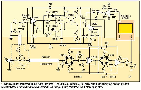
sequential-sampling oscilloscope plug-in module can significantly increase the
display bandwidth of an ordinary 10-MHz oscilloscope for repetitive signals
(Fig. 1).


Using the 5KΩ potentiometer and
oscilloscope adjustments, the time base is adjustable from 1 to 50nS/div. For
longer sweeps, the circuit should simply be bypassed, and the oscilloscope must
be used directly. By adding a DSO board and computer, it can be converted into
a digital sampling oscilloscope as well. Future modifications, such as the use
of the strobe as a variable delay generator, are simple to put into effect.
Also easily implemented is the “synchroscope” mode, with triggerable components
installed within the delay line.
The input
signal enters via the compensator box, which is a 4.6-dB pole zero cancellation
attenuator.(ref 1) In essence, the 40pF capacitor diverts fast changes into the
40nS RG58A/U 50Ω delay line, (about
26' or 27' for Teflon), and away from the inductor arm. As was verified by
using this sampler as a time-domain reflectometer (TDR), the two main ports are
50Ω up to 1 GHz. Frequency-dependent
losses in the delay cable are quite accurately compensated, as shown by the
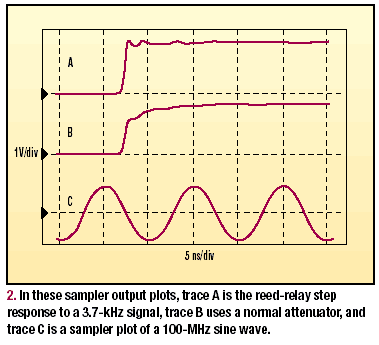
reed-relay (Radio Shack part number 275-232) step response (Fig. 2, trace A).
When an ordinary 4.6dB attenuator is implemented, a rounded step response
results (Fig. 2, trace B).
Although
the inductor arm derives the trigger from the input signal, other triggers can
be plugged in as needed. These triggers also can be displayed by routing them
to the sampler via the delay line. For each input pulse, the MAX961 trigger-and-hold
comparator triggers an adjustable-rate, fast-ramp circuit by switching the two
Schottky clamped MPSH10 transistors. At
the same time, its 4V complementary-output step quickly enables its own latch
(LE), locking out further changes. This locked comparator allows the switched MPSH81 current source to
ramp up the 82pF capacitor from -2V to 2V, without interruption. After 500nS,
the resistor discharges the 1nF capacitor to 0V, thereby reinstating the
comparator and re-arming the ramp.
The plus
input of the MAX961 strobe comparator
is scanned by either a slow ramp from the oscilloscope time-base output (T), or
the 250-WO manual control (X) for the X-Y plotter. It’s scanned over the same
voltage range of -2V to 2V, which also is used as the display horizontal
signal. Each time the fast ramp crosses this voltage , the comparator output
switches from 2V to -2V. Meanwhile, its complementary output switches from -2V
to 2V. Both outputs maintain a specified transition duration of 2.3nS. They
also symmetrically drive the master/slave track-and-hold bridges that are connected
to sequentially sample VIN in the delay cable. The actual sampling
event happens in the track-to-hold transition. It takes place during the few
hundred picoseconds in which the master MBD301 Schottky
diode bridge resistance switches from low to high. Such switching occurs
within a small, central part of the full 8V applied step.
Consequently,
its switching duration must be only a small fraction of the strobe comparator
transition duration. The RC delay network controls the strobe comparator's
latch. While the slave is in the track mode, this latch locks the master T/H,
(Track and Hold), in the hold state for 650nS.
During
this 650nS period, the master BIFET charge amplifier (˝TL082 4MHz unity
gain) can buffer the sample, pulsed onto its input capacitance of about
15pF. This voltage is a scaled-down replica of the sampled voltage entering the
1pF/15pF capacitive divider. A 15MΩ/1MΩ resistive divider is connected across it, which
completes this wideband compensated attenuator. Therefore, the master bridge is
loaded with only a low-input capacitance of about 1pF. Because the bridge's
on-resistance is about 100Ω, the RC time
constant is around 100pS.
Continuously
buffering the 1nF memory, the slave T/H BIFET amplifier (˝TL082) produces a
step-like, down converted representation of the input waveform (VIN).
It does so at a low intermediate frequency (IF) for the oscilloscope, or a zero
IF for the X-Y plotter. Switching transients are eliminated via the adjustable
low-pass filter (LPF). By averaging the output over as many input pulses as
desired, this device strongly reduces noise.
The
bandwidth of this sampler is over 1GHz. Its transition duration is about 300pS
which, together with the approximately 250pS intrinsic risetime of the reed
relay, yields the measured display transition duration of 400pS (Fig. 2, trace
A, again). Trace C illustrates the time-scale calibration and vertical-scale
linearity by showing a sampled 100MHz sine wave with a sampled zero line. For
this RF measurement, a countdown trigger was used, prior to the
trigger-and-hold.(ref 2) To display higher frequencies with this sampler, the
countdown trigger should be preceded by a prescaler, such as the
emitter-coupled logic (ECL) circuitry.(ref 3) Additional experiments have
verified that its fairly easy to add more synchronized channels, using the
strobe comparator to fan out and drive two or more similar comparators. Via
separate delay lines, each of these comparators drives individual T/H circuits
to sample multiple inputs.
Comments
by me, redrok:
I believe the "Resistive Splitter" started out as an "Adams'
type Un-Equal resistive splitter". It probably had a 4.6db main loss with
a 10db pick off for the compensator. This would have had a pair of 13Ω and a 54Ω resister in the
"Y" connection. See [5].
However, as with all microwave circuits, there are numerous "Magic"
components we can't see. So Houtman tweaked the design with:
1. Adding a 40pF speedup cap.
2. The 54Ω was changed to 40Ω and a matching
inductor to the 50Ω coax going to the
trigger comparator.
This probably results in less main loss and less going to the pick off.
The MAX961 trigger comparator
doesn't need very much amplitude to work well. Also the MAX961 has about 3.5mV of
hysteresis.
The MAX961 trigger comparator
triggers on a rising edge. If you want to trigger on a falling edge just
reverse the inputs. This could be done with a small DPDT reed relay or tiny
switch.
The AVAGO HSMS-282x series of Schottky
diodes are superior to the MBD301 especially for the sampler bridges. Use the
HSMS-282P or HSMS-2828.
I intend
to use a MicroMite MK2 controller to drive the sampler. It is programmed in a
very capable version of BASIC. The uMite has a 10bit AtoD converter and an OLED
graphic display. I will be using several I2C 10bit DtoA to control the trigger
level, Slope, and Sample level. I like the MCP4716 although 8bit or
12bit versions could also be used.
References:
[1] G.
Amsel, R. Bosshard, R. Rausch, and C. Zajde, “Time Domain
Compensation Of Cable Induced Distortions Using Passive Filters For The
Transmission Of Fast Pulses,” Review of Scientific
Instruments, Vol. 42, No. 8, p. 1237-1246, August 1971.
[2] H.
Houtman, “Counter Circuit
Improves Oscilloscope Triggering,” Electronic Design, Vol. 48,
No. 15, p. 126, July 2000.
[3] F.J.
Hufft, “Build This 1.6-GHz
Counter Presale,” Radio-Electronics, Vol. 61, 10, p. 47-54, October
1990.
More
references added by me:
[4] H.
Howe, “Stripline circuit design”, 1974, Artech House.
(Invaluable "Must Have" book!!!!)
[5] "Adams'
Un-Equal resistive splitter"
"Adams
Calculator for un-equal splitters"
[6] "DIY Ghz
sampling head for greater than 100Mhz scopes"
[7] "Generation of short electrical
pulses based on bipolar transistors"
[8] "SAMPLING
NOTES"