Volkswagen 01M Transmission. Manual - part 40
19
Technical Service Information
A-3
2
2
2
2
AISIN
AISIN
AISIN
AISIN
8 8
6 0
8 8
6 0
8 8
6 0
8 8
6 0
1
1
1
1
9A
N3K
01755
9A
N3
K0
1762
8B
A3K
016
31
9A
N3K
01748
9A
N3K
017
42
4A
M
3K
03O
18
142
7
AT
JP
57344-0
1
09D 321 361
>F
e/Zn
<
24
15
84
54
0
TR
A0
10
Transaxle
(Multifunction F125)
Range Switch
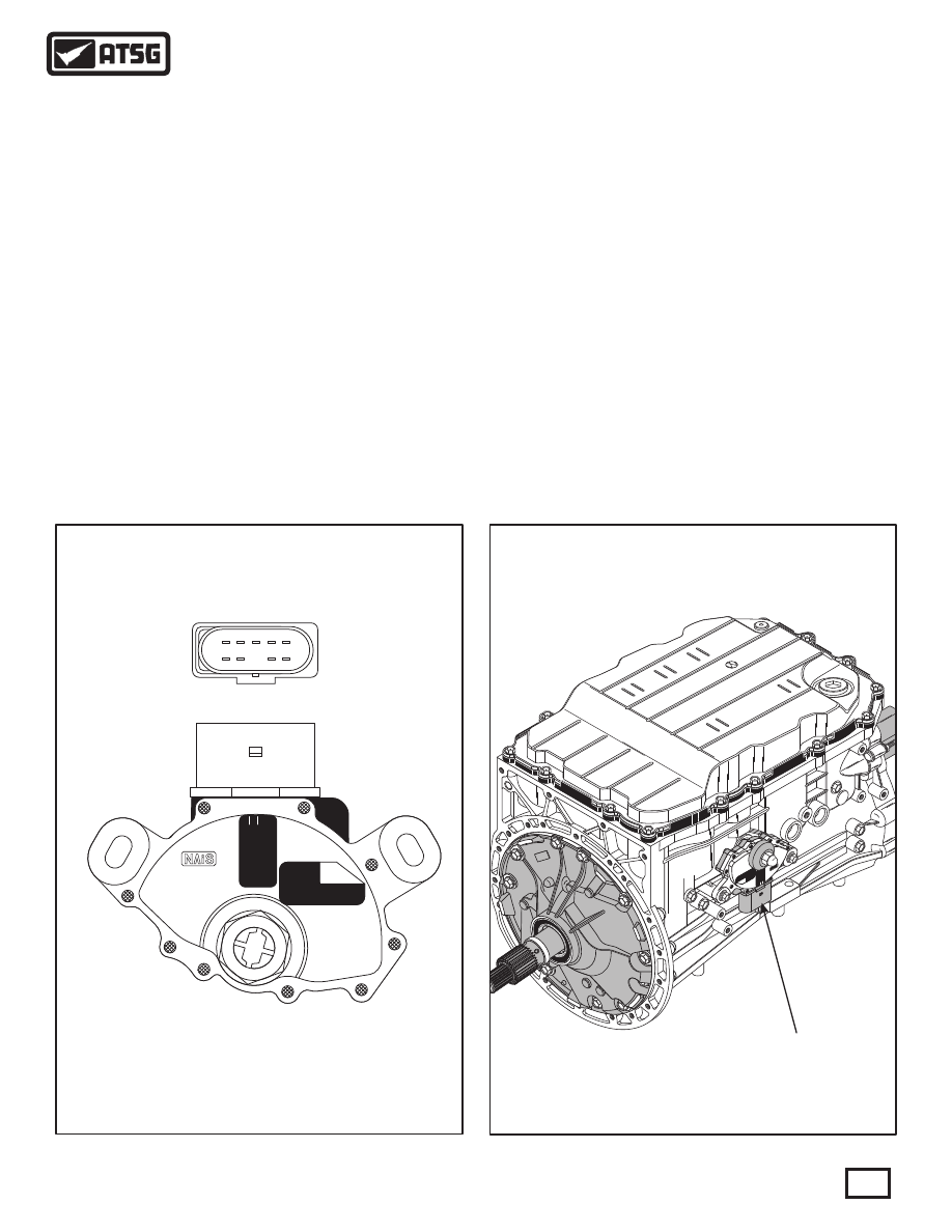
Figure 23
Figure 22
TRANSMISSION RANGE SWITCH LOCATION
TRANSMISSION RANGE SWITCH
(MULTIFUNCTION SWITCH F125)
ELECTRONIC COMPONENTS (CONT'D)
Transmission Range Switch (Mulitfunction F125)
Diagnosis
Diagnosis (Cont'd)
The Transmission Range Switch (TRS) is located on
the right hand side of the transmission, as shown in
Figure 23. The TRS is a mechanical multi-position
switch with 6 sliding contacts, four selector position
switches, one reverse switch and one switch for
positions P/N, for starting control.
The TRS is shown in Figure 22 and if removed or
replaced, a position to the selector (manual) shaft
must be set using special tool from Volkswagen.
The only ignition voltage sent to the switch goes in at
terminal 10 and goes through only the reverse switch,
as shown in Figure 24. Voltage exits through terminal
8 and is sent to the reverse lamps and the TCM.
Diagnosis here is easily done using a volt meter.
The remainder of the switches provide a ground
signal for the starter relay through the P/N switch and
ground signal to the TCM through the position
switches, as shown in Figure 24. These switches
must be checked with the DVOM set to Ohms. Notice
in Figure 24 that terminals 3 and 4 provide the ground
into the switches. Use the Ohm meter across
terminals 4 and 2 to check for the Park and Neutral
positions, as shown in the chart provided in Figure 24.
With the Ohm meter on terminal 3, you should have
continuity across the terminals shown in the chart in
Figure 24, related to the position of the gear selector
lever.
2415
84540
TRA010
1
2
3
4
5
6
7
8
9
10