Volkswagen 01M Transmission. Manual - part 48
51
Technical Service Information
467
13
468
469
469
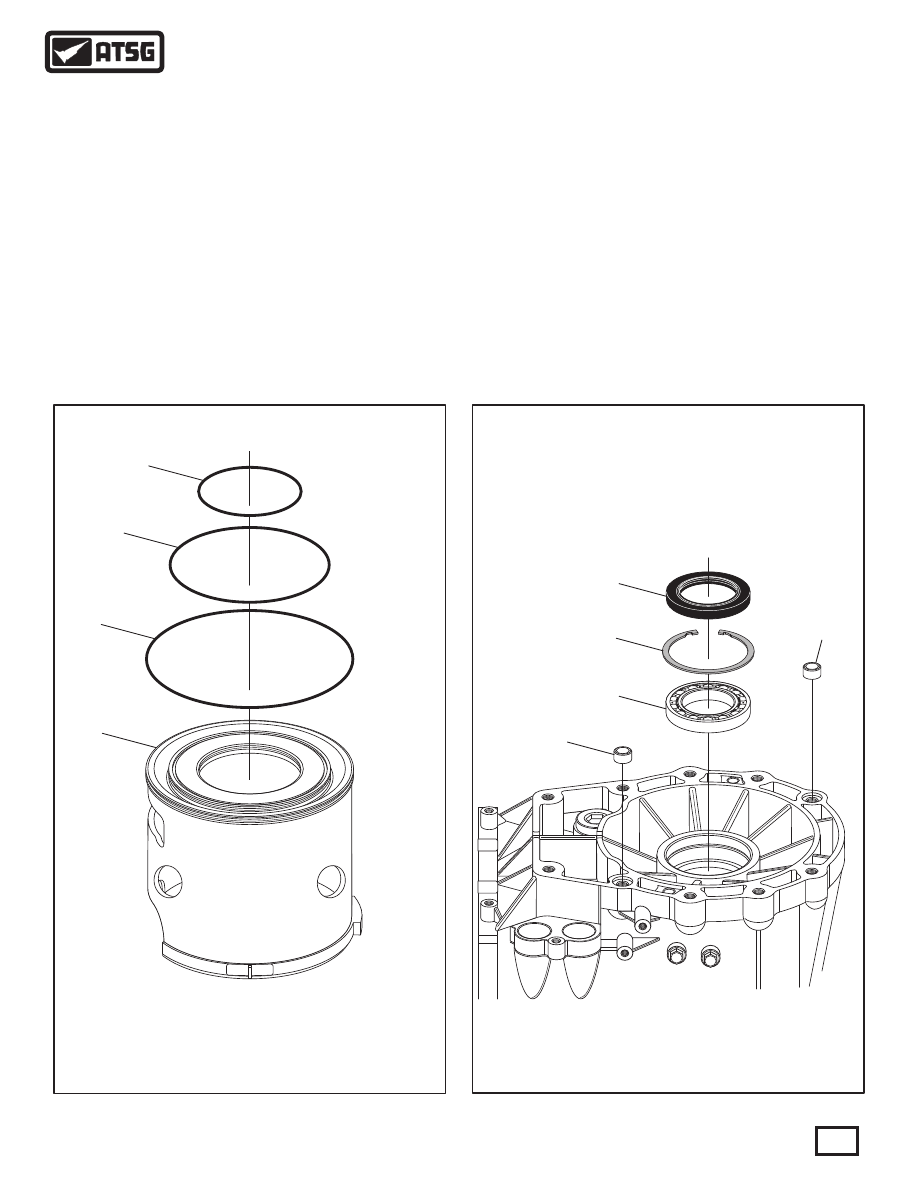
13 REAR TRANSMISSION SEAL.
467 REAR BALL BEARING RETAINING SNAP RING.
468 REAR BALL BEARING.
469 HOLLOW DOWEL PINS (2 REQUIRED).
424
425
426
427
424 B2 CLUTCH APPLY PISTON.
425 B2 CLUTCH PISTON OUTER "O" RING SEAL.
426 B2 CLUTCH PISTON INTERMEDIATE "O" RING SEAL.
427 B2 CLUTCH PISTON INNER "O" RING SEAL.
Figure 77
Figure 78
76. Remove and discard the three "O" ring seals on
the B2 clutch piston, as shown in Figure 77.
77. Remove and discard the rear transmission seal,
as shown in Figure 78.
78. The rear transmission bearing is retained with a
snap ring, as shown in Figure 78.
79. Replace the rear transmission ball bearing as
necessary.
Note: The 2WD and 4WD rear ball bearings
have different inside diameters.
TRANSMISSION DISASSEMBLY (CONT'D)
This Concludes
Transmission Disassembly