Volkswagen 01M Transmission. Manual - part 119
 

  Index      Volkswagen     Volkswagen 01M Transmission - service manual 2001 year


Search              


Content   ..  117  118  119  120   ..


Volkswagen 01M Transmission. Manual - part 119


Continued on Page 107

106

Technical Service Information

7

4051 - 1 - 1

03C2T02168

Z

0

300  035H

09G

1004

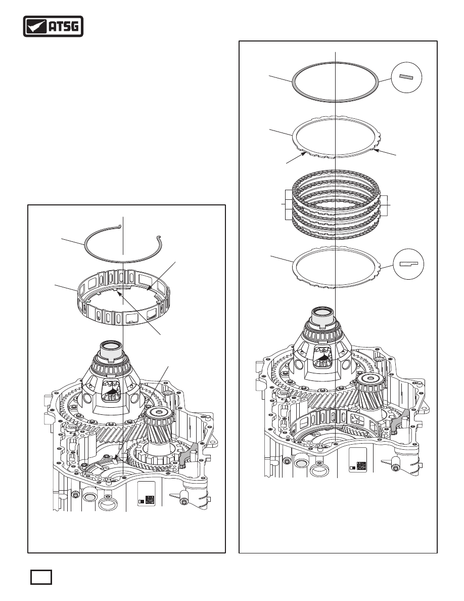
Figure 177

426

THIS OPENING
TOWARDS THE

TRANSFER GEAR

ENSURE THESE LUGS

ARE ENGAGED IN

THESE SLOTS

427

 426  B1 CLUTCH HOUSING RETAINING SNAP RING.
 427  B1 CLUTCH HOUSING.

0

1

7

4051 - 1 - 1

03C2T02168

Z

0

300  035H

09G

1004

Figure 178

424

425

422

421

423

 421  B1 CLUTCH "BELLVILLE" CUSHION SPRING.
 422  B1 CLUTCH BACKING PLATE, STAMP 10, 2.52MM (.099") THICK.
 422  B1 CLUTCH BACKING PLATE, STAMP 3, 2.4MM (.095") THICK.
 423  B1 CLUTCH FRICTION PLATES  (QTY MAY VARY).
 424  B1 CLUTCH STEEL PLATES, 1.8MM (.071") (QTY MAY VARY).
 425  B1 CLUTCH "STEPPED" PRESSURE PLATE, 2.9MM (.114") THICK.

TRANSAXLE FINAL ASSEMBLY (CONT'D)

 26. Install the B1 clutch housing with the opening
       towards the transfer driven gear, as shown in
       Figure 177, and insure lugs are engaged in slots
       in the center support.
 27. Install the B1 clutch housing retaining snap ring
       with opening towards the transfer gear, as shown
       in Figure 177, and ensure it is fully seated in the
       center support.
       Note: This snap ring is identified by two small
       "turn-outs" at the snap ring ends, as shown in
       Figure 177.

ROUNDED EDGE

FACING DOWN

ID STAMP

8

Continued on Page 108

107

Technical Service Information

7

10

4051 - 1 - 1

03C2T02168

Z

0

300  035H

09G

1004

Figure 179

131

134

133

132

REAR VIEW

 120  NUMBER 5 THRUST BEARING RACE.
 131  K1 CLUTCH HOUSING ASSEMBLY.
 132  NUMBER 6 THRUST BEARING.
 133  NUMBER 6 THRUST BEARING RACE.
 134  K3 CLUTCH HOUSING DRIVE HUB.

 28. Install the B1 clutch "stepped" pressure plate, as
       shown in Figure 178, with "step" facing down.
 29. Install B1 clutch pack beginning with a friction
       plate onto the pressure plate and alternating with
       a steel plate, as shown in Figure 178, until you
       have installed the proper quantity, as the quantity
       may vary.
       Note: All friction plates should be soaked in
       proper fluid for 30 minutes before installing.
 30. Install the B1 clutch backing plate on top of the
       last friction, as shown in Figure 178, with the
       rounded edge facing the friction.
       Note: Notice the number stamped on top side
       of backing plate, which is an indicator that it
       is selective, but no selectives available as yet.
 31. Install the B1 clutch "bellville" cushion plate in
       the direction shown in Figure 178.
       Note: There is no backing plate snap ring for
       the B1 clutch pack.  We will check B1 clutch
       clearance before installing oil pump, as the
       apply piston is in the oil pump assembly.  The
       apply piston caged return spring assembly sits
       between the piston and cushion plate, retaining
       the B1 clutch pack.
 32. Install K3 clutch housing drive hub, as shown in
       Figure 179, and engage on splines of sun gear.
 33. Install the number 6 thrust bearing race into the
       drive hub, as shown in Figure 179.
 34. Install the number 6 thrust bearing with needles
       facing down, as shown in Figure 179.
 35. Install completed K1 clutch housing, as shown
       in Figure 179.
 36. Ensure that number 5 thrust bearing race is still
       in place on K1 clutch housing, as shown in
       Figure 179.

TRANSAXLE FINAL ASSEMBLY (CONT'D)

120

 40. Install the B1 clutch apply ring and return spring
       assembly, as shown in Figure 181.
       Note: Return spring assembly goes around the
       outside diameter of K3 clutch housing and 
       seats on B1 clutch cushion spring.

108

Technical Service Information

113

111

7

8

4051 - 1 - 1

03C2T02168

Z

0

300  035H

09G

1004

Figure 180

 111  NUMBER 2 THRUST WASHER.
 113  FRONT PLANETARY ASSEMBLY.
 119  NUMBER 5 THRUST BEARING.

7

4051 - 1 - 1

03C2T02168

Z

0

300  035H

09G

1004

420

100

Figure 181

 100  K3 CLUTCH HOUSING ASSEMBLY.
 420  B1 CLUTCH APPLY RING AND RETURN SPRING ASSEMBLY.

Continued on Page 109

 37. Install the completed front planetary assembly,
       as shown in Figure 180, ensuring that number 5
       thrust bearing and number 2 thrust washer are
       still in place.
 38. Front planetary assembly must be rotated back
       and forth to engage K1 clutch frictions into the
       planetary hub until fully seated.
 39. Install K3 clutch housing assembly, as shown in
       Figure 181, by rotating back and forth until it is
       fully seated.
       Note: K3 clutch frictions must engage on the
       front planet hub, K3 clutch housing must be
       engaged into B1 frictions and drive hub.

TRANSAXLE FINAL ASSEMBLY (CONT'D)

119

REAR VIEW

7

4051 - 1 - 1

03C2T02168

Z

0

300  035H

09G

1004

109

Technical Service Information

Figure 182

7

4051 - 1 - 1

03C2T02168

Z

0

300  035H

09G

1004

3

4

5

1

2

S

t

t

ar

t

re

9

8

0

TRANSAXLE FINAL ASSEMBLY (CONT'D)

 41. Measure the distance from case pump surface to
       the washer surface on the K3 clutch housing, as
       shown in Figure 182, using a straight edge and
       ruler, or a depth micrometer.
       Note: This measurement should match the
       measurement taken on disassembly to ensure
       that K3 clutch housing is fully seated.
 42. Install "H" gage on transaxle pump surface, as
       shown in Figure 183, lower the adjustment rod
       to the piston surface (See Inset in Figure 183)
       of the B1 apply ring/return spring assembly and
       tighten the adjustment rod locking knob.
 43. Now turn the "H" gage over and set it on the
       completed oil pump assembly, "with" the new
       design gasket, as shown in Figure 184.
 44. Measure with feeler gauge between adjustment
       rod and B1 clutch piston to determine the B1
       clutch clearance.
 45. B1 clutch clearance should be approximately
       0.26 mm (.010") per friction plate installed.

Figure 183

Figure 184

Continued on Page 110

B1 Clutch Clearance Should Be

Approximately 0.26 mm (.010")

Per Friction Plate Installed

ADJUSTMENT

ROD

RETURN
SPRING

ASSEMBLY


Content   ..  117  118  119  120   ..