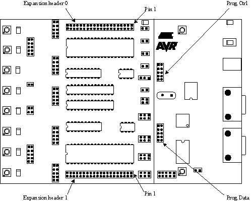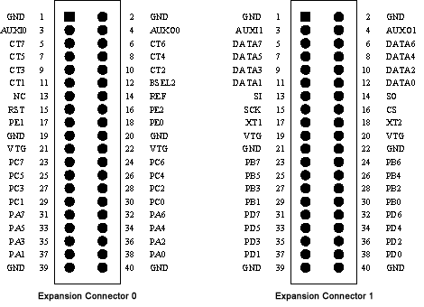

STK500 has two expansion connectors, one on each side of the programming module. All AVR I/O ports, programming signals, and control signals are routed to the expansion connectors. The expansion connectors allow easy prototyping of applications with STK500. The pinout of the expansion connectors is shown in the figure below.

The signals AUXI1, AUXI0, AUXO1 and AUXO0 are intended for future use. Do not connect these signals to your application.
The DATA[7:0] and CT[7:1] signals are also found on the Prog Data and Prog Ctrl con-nectors. These signals and connectors are explained in "Prog Ctrl and Prog Data Headers".
The BSEL2 signal is the same that is found on the BSEL2 jumper. This jumper is explained in BSEL2 Jumper.
The SI, SO, SCK and /CS signals are connected to the dataflash. Use of the dataflash is described in Description of Dataflash Pins.
NC means that this pin is not connected.
The remaining signals are equal to those found on the PORT connectors explained in Port Connectors.
Note: DATA, CT and AUX signals are based on 5V CMOS logic. No voltage conversion to adapt to VTG is done on these signals.
See Also