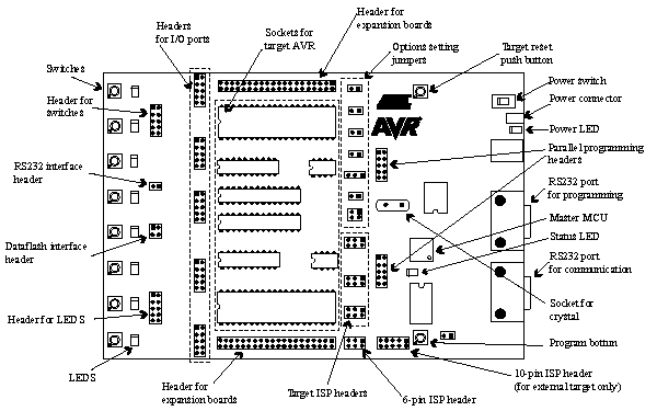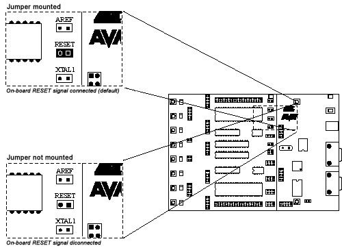

The RESET jumper controls the RESET signal to the STK500. When ISP programming the target device in the socket, the master MCU programs the AVR device without interfering with the application. When the RESET jumper is mounted, the master MCU controls the RESET signal of the AVR. When the RESET jumper is not mounted, the RESET signal is disconnected. This is useful for prototype applications with an external reset system.
The RESET jumper must always be mounted when High-Voltage programming an AVR device. When using an external reset system it must allow the reset line to be controlled by the master MCU reset system during programming. The RESET button is disconnected if the RESET jumper is not mounted. The figure below explains the RESET jumper options.

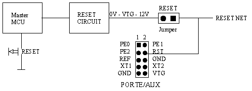
The STK500 master MCU controls the RESET signal to the target AVR. The RESET signal is accessible on the PORTE/AUX header; this pin can also be used for external RESET signal. The figure below shows the internal connection of the RESET signal.

Note: During High-Voltage Programming, STK500 applies 12V to the AVRís RESET line. Thus, an external reset circuit not capable of handling this must be disconnected before High-Voltage programming the AVR.
See Also