In-System Programming uses the AVR internal SPI (Serial Peripheral Interface) to download code into the flash and EEPROM memory of the AVR. ISP programming requires only V CC , GND, RESET and 3 signal lines for programming. All AVR devices except AT90C8534, ATtiny10, Attiny11 and ATtiny28 can be ISP programmed. The AVR can be programmed at the normal operating voltage, normally 2.7V-6.0V. No high voltage signals are required. The ISP programmer can program both the internal flash and EEPROM. It also programs fuse bits for selecting clock options, startup time and internal Brown Out Detector (BOD) for most devices.
High-Voltage programming can also program devices that are not supported by ISP pro-gramming. Some devices require High-Voltage programming for programming certain fuse bits. See the High-Voltage programming section for instruction how to use High-Voltage programming.
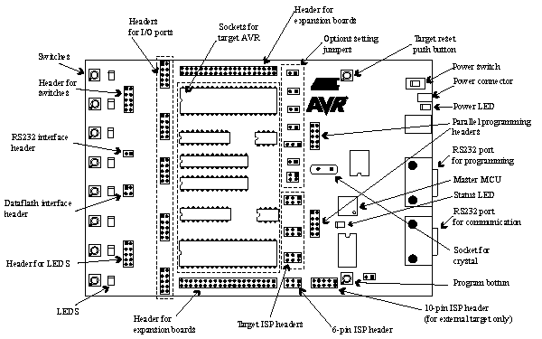
Because the programming interface is placed on different pins from part to part, 3 pro-gramming headers are used to route the programming signals to the correct pins. A 6-wire cable is supplied for connecting the ISP signals to the target ISP header. A color coding system, and a number system, is used to explain which target ISP header is used for each socket.
During ISP programming the 6-wire cable must always be connected to the header marked ISP6PIN. When programming parts in the blue sockets, connect the other end of the cable to the blue SPROG1 target ISP header. When programming parts in the green socket, use the green SPROG2 target ISP header. And when programming parts in the red sockets, use the red SPROG3 target ISP header. The table below shows which socket suits which AVR device, and which SPROG target ISP header to use for ISP programming.
The 6-wire cables should be connected directly from the ISP6PIN header to the correct SPROG target ISP header. The cable should not be twisted. A colored wire on the cable indicates pin one. Confirm that this is connected to pin one on each of the headers.
When programming 8-pin devices, note the following: Pin 1 is used both as RESET and as PB5 on some devices (ATtiny11, ATtiny12 and ATtiny15). Pin 1 on the 8-pin sockets SCKT3400D1 and SCKT3400D1 are connected to PB5. The RESET signal used during ISP programming is therefore not connected to pin 1 on these sockets. This signal must be connected by placing a wire between RST and the PORTE header and PB5 on the PORTB header.
| AVR devices | STK500 socket | Color | Number | Target ISP header |
|---|---|---|---|---|
| AT90S1200 AT90S2313 |
SCKT3300D3 | Red | 3 | SPROG3 |
| AT90S2323 AT90S2343 ATtiny12 ATtiny22 | SCKT3400D1 | Blue | 1 | SPROG1 |
| ATtiny11 | SCKT3400D1 | Blue | 1 | High-Voltage programming only |
| ATtiny28 | SCKT3500D- | None | - | High-Voltage programming only |
| AT90S4414 AT90S8515 ATmega161 | SCKT3000D3 | Red | 3 | SPROG3 |
| AT90S4434 AT90S8535 ATmega163 ATmega32 | SCKT3100A3 | Red | 3 | SPROG3 |
| AT90S2333 AT90S4433 | SCKT3100A3 | Green | 3 | SPROG2 |
| ATtiny15 | SCKT3600A1 | Blue | 1 | SPROG1 |
| N/A | SCKT3700A1 | Blue | 1 | Socket is not in use in this version of STK500 |
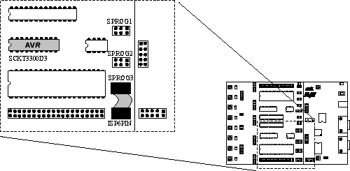
The figure below shows an example of how AT90S2313 can be In-System Programmed. The 6-wire cable is connected from the ISP6PIN header to the red SPROG3 target ISP header, and the AT90S2313 part is inserted in the red socket marked SCKT3100D3.
It is not necessary to remove the 6-wire cable from its ISP position while running a pro-gram in the AVR. The port pins used for ISP programming can be used for other purposes in your program.
See Also